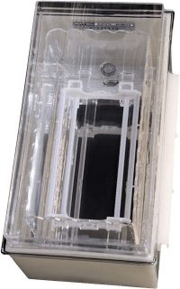
Quartz Megasonic
Cleaning Tank
概述
Accumeg™ megasonic cleaning technology has been shown to be an essential performance element in advanced cleaning applications. Combining over 40 years of industry know-how with some of the most reliable megasonic tank components available, IMTEC has designed a cleaning system for a wide-range of high-purity processes. The Accumeg is designed to provide continuous megasonic energy across the full width and depth of all the substrates in the process tank. This constant energy is the key to complete, fast, efficient megasonic cleaning and the elimination of particle reattachment.
Unlike other systems, which use “pulsed" megasonic transducer arrays in an attempt to achieve even, full coverage, the Accumeg megasonic transducer array covers the entire process load capacity of the tank without any of the energy loss associated with “shadowing" or “sequencing".
Backed by our extensive 36 month warranty, IMTEC’s Accumeg series offers the reliability and productivity that ensures excellent uptime, minimum maintenance and the lowest cost of ownership.
特點和優點
- Reliable components, extensive 36 month warranty
- Cassette & cassette-less designs for up to 300 mm wafers & larger substrates
- Field replaceable transducer arrays
- High watt density
- Operates at 70°C+
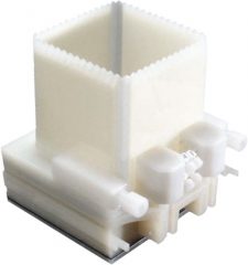
PVDF Megasonic
Cleaning Tank
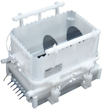
PVDF Megasonic Tank with Quick Dump Rinse
Megasonic Cleaning Technology
“Gapless" Transducer – For better process uniformity in the tank, the piezoelectric crystals on the transducer should be installed as close together as possible. However, when each crystal is wired to the generator individually, they must be spaced at least 1mm apart to avoid arcing that shorts out the transducer.
IMTEC uses superior transducers with tightly matched crystals wired together in parallel. This means that there is a small potential difference between crystals and they can be placed close together- 0.1mm apart- without risk of shorting.
Megasonic Quick Dump Rinse Bath (QDR) – To quickly remove chemical and particulate from a bath after a process run, IMTEC developed and patented the QDR Accumeg. Rather than disturbing the bottom of the bath where the transducer is mounted, the IMTECsystem raises the walls of the bath, allowing the chemical to flow out evenly and rapidly, and without allowing any particulate settled at the bottom of the bath to re-attach to the substrate. This “tank lift" system maintains a clean environment and saves valuable processing time. To learn more about megasonics and how they can improve your process please visit the download tab for more resources.
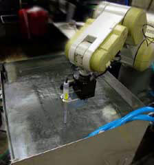
Megasonic tank energy uniformity test with probe and robotics
Megasonic Cleaning vs. Ultrasonic Cleaning
As wafer structures become smaller and more complex, Ultrasonic energy is becoming increasingly undesirable in the Semiconductor market. The high cavitation energy produced in Ultrasonic cleaning can blow out sensitive structures and damage substrates. The gentler cleaning energy produced by Megasonic waves can dislodge particles without damaging sensitive devices.
In a sonic cleaning system, a transducer generates high frequency vibrations in a fluid medium. These high frequency vibrations, as described below, create a scrubbing action on a substrate uniquely suited to cleaning devices with crevices or blind holes such as semiconductors or memory disks
The transducer mounted on the outside of the tank produces high frequency waves that propagate through the fluid medium. Each point along the wave oscillates between a maximum and minimum pressure. When the pressure minimum is below the vapor pressure of the fluid medium, bubbles are formed in the fluid medium. When the pressure increases to maximum pressure, the bubbles implode, sending out an intense shockwave of energy as the fluid rushes in to fill the void left by the collapsed bubble. This energy is referred to as cavitation energy, and is well-suited for dislodging particles or contaminants from a substrate.
Many factors can affect the intensity of the cavitation energy in a sonic process, such as the surface tension of the fluid medium, or the distance of the substrate from the transducer. However, a critical factor is the frequency of the sonic waves. In a typical Ultrasonic cleaning process, the transducer emits a frequency of less than 100kHz. This lower frequency means that bubbles have a longer time to form and grow, creating more cavitation energy when they collapse. Megasonic processes utilize frequencies from 600-2000 kHz. These higher frequencies mean that bubbles have less time to grow and are smaller when they collapse, producing a proportionally smaller amount of cavitation energy.
Megasonic Quick Dump Recommendations
The purpose of the Accumeg quick dump process is to remove, or keep suspended, any trace ionic species and/or particulate contaminants carried over from prior process steps that are held in the fluid boundary layer surrounding the wafers. The QDR rinse sequence is also critical for cleaning the QDR process vessel walls and cassette. While there are many processes which benefit from megasonic quick dump enhancement, two representative processes are shown in the table below. Process A is typical of quick-dump rinse that follows a prior cool process (under 100°C), while Process B similarly describes a quick-dump rinse that follows a prior hot process (over 100°C). The following table presents the general requirements for these two typical processes. Following the Table of General Process Requirements, is a more detailed recommended process sequence for both A and B is given.
General Process Requirements
A |
Time/Temp/Flow Set points for Rinsing immediately following an under-100°C prior process [Examples: Post SC1 (NH4OH+H2O2+DI H2O) or SC2 (HCL+H2O2+DI water) Cleans] |
|
|---|---|---|
B |
Time/Temp/Flow
Set points for Rinsing immediately following an over-100°C prior process [Examples: Post Hot Piranha (H2SO4+H2O2+DI water) or Hot Phosphoric (H3PO4) applications] |
|
C |
Megasonic Power Requirements |
|
A and B Processes: Recommended Flow Description
- Both processes commence by dumping the process vessel contents held over from last step of the prior batch (Step 15);
- The Megasonic Quick Dump process vessel is filled using top spray and bottom fill manifolds and is permitted to overflow for thirty (30) seconds;
- The top spray is turned off and the megasonic power is turned on;
- The wafer load is inserted;
- With the megasonic power on, the wafer load is held in the overflowing quick dump rinse process vessel for approximately five (5) seconds;
- DI-water top spray is turned on; (Note: the DI bottom fill remains on)
- The process vessel quick dump is activated;
- Megasonic is turned off; (Note: DI water remains on)
- Quick Dump closes after approximately four (4) seconds;
- Once the water-fill level is approximately 6 mm above the transducer, the megasonic power is turned on;
- With the megasonic power on, the process vessel continues to be filled by both the top spray and bottom fill;
- Once filled, the process vessel is allowed to overflow for approximately 5 seconds and then again dumps;
- The above megasonic-rinse sequence (Steps 8 through 12) is repeated for the minimum number of cycles recommended for the particular A or B process (See Recommended Process Parameters in preceding chart);
- In the last cycle, the process vessel does not dump but remains in overflow mode with the megasonic power and DI bottom fill on, and the DI top spray off, while the wafer load is removed from the QDR and proceeds to its next process step;
- Once the wafer load has been removed from the ACCUMEG Quick Dump Rinser, the megasonic power and DI-water fills are turned off (except for a trickle purge of approximately 4-6 L/hr which is required to remain on at all times). The system remains in this standby condition, ready for the beginning of the next cycle.
Megasonic Equipment Specifications
Megasonic Tank & Transducer Specifications
Model specific information is supplied with each system.
- Megasonic Frequencies: 975 & 730 kHz (+/-25 kHz) model dependent
- Tank Materials: Quartz, PVDF, or PFA
- Megasonic Transducer Plate: 316 L Electropolished or PFA PTFE coated Stainless
- Megasonic Transducer Cables: 25 ohm PTFE jacketed, 5 meter length
- Maximum operating temperature for Boundary layer system: 130°C*
- Maximum operating temperature for direct systems: 70°C
- Operating Voltage: 208-230 VAC +/- 10% single phase
- Limited Warranty: 36 months
- Applicable Standards: Meets all applicable CE directives, 3rd party certified
*Requires adequate boundary layer cooling to keep transducer at 80°c or less.
Megasonic Generator Specifications
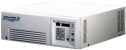
Model |
Megasonic Generator |
|---|---|
Rated Output Power |
1200 Watts |
Output Range |
60~1200 Watts |
Oscillation System |
Crystal controlled synthesizer |
Rating Power Supply |
208-230Vac ±10%, 10A, single phase 50 or 60Hz |
Remote Control |
RS-485 or Discrete I/O control |
External Dimensions (WxDxH in mm) |
380 x 550 x 175 |
Weight |
< 25kg |
Operating Ambient Condition |
5-40°C |
*Not including connectors, fan, switches, and other projecting parts. legs are included in dimensions.


