Overview
Ultrasonic/megasonic cavitation meters (0 to 5 MHz) are precise instruments for measuring ultrasonic/megasonic and cavitation energy density, as well as the ultrasonic/megasonic frequency. The systems measure energy density at a given point in time and space in a single fixed direction in the tank. The meters are simple and easy to use yet contain sophisticated electronics for data storage, retrieval and analysis. Readings are processed 1.5 times per second for fast accurate display on the front panel LCD.
In “auto mode" the unit will gather statistical parameters including average, standard deviation, minimum and maximum readings. This allows you to establish several strategies to characterize a tank. Data collection strategies include:
- Measuring energy variations at a given point in the tank as a function of time.
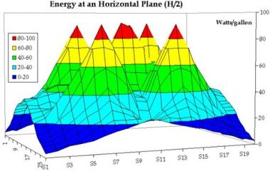
- Mapping a tank by ‘walking’ the probe at a fixed depth under the surface of the tank. See an example below “Mapping Energy".
- Comparing average energy from tank to tank, over the life of a tank, or unloaded versus loaded with parts to be cleaned.
Mapping Energy

Objective
To profile the cavitation energy at an horizontal plane in a DI water tank.
Procedure
An ultrasonic probe is walked in the horizontal XY plane at half the distance between the surface of the water and the ultrasonic transducer. Data is collected at each X,Y coordinate for 10 seconds and the 10-second average is recorded.
Method
A tank measuring 13.5” long, by 9.5” wide, by 10” deep is used. This tank contains 5.85 gallons of DI water sonicated by a 40 kHz ultrasonic transducer rated at 500 watts.
The transducer is 9” long, by 6.5” wide, by 3” deep. The 316 stainless steel box contains actually 5 transducers inside it operating at about 100 watts each.
The tank is filled with 5.85 gallons of de-ionized water and sonicated for 30 minutes for de-gassing. The water temperature is recorded at 20° centigrade throughout the experiment. The water depth is 6.7”. The surface of the probe is kept parallel to the bottom of the tank at 3.7” from the top lip of the tank.
Setting the cavitation meter in AUTO mode, the probe is located at one corner of the tank and run for 10 seconds. The probe is then re-located 0.5” away from its previous position in order to walk it along the X (longitudinal) axis at a fixed Y (latitude). This procedure is repeated until 560 data points have been obtained.
The data is down-loaded 100 data points at a time to a PC using excel format.
Results
The data shows that there is an uneven distribution of cavitation energy at the half-height of the DI tank. There are 4 minima, one at each corner of the tank at about 6 watts per gallon. There are 4 peaks, one on top of each transducer at about 200 watts per gallon. The average energy at this plane is 78 watts per gallon.
Discussion
This method of profiling cavitation in a tank can be useful in establishing the variations in energy density. It is also useful to obtain the average cavitation energy of the tank.
Specifications
Energy Range |
0 to 255 w/in2 (w/gal*) |
|---|---|
Energy Accuracy |
±0.2% w/in2 (w/gal) |
Energy Display Resolution |
1.0 w/in2 (w/gal) |
Frequency Range |
0 to 5 MHz (2000 kHz) |
Frequency Accuracy |
±1.0 kHz |
Freq. Display Resolution |
0.1 kHz |
Display |
Custom LCD |
Memory |
100 sets: loc., date, time, avg., max,min, DT, freq. |
Output |
Computer or Serial printer interface (9600, 8,1, n, p) |
Input |
Standard 7.2-volt battery charger, Probe |
Case Materials |
Aluminum with polyurethane baked enamel paint |
Probe Materials |
Contact sales representative for details. |
Operating Temperatures |
1° to 100° C (33° to 392° F) |
Power |
One 7.2-volt sealed Ni-MH rechargeable battery |
Weight |
2 lb. Complete |
Case Dimensions (WxLxH) |
4 x 8 x 2 inches |